Key Takeaways
- Oriented silicon steel carries magnetic flux far more easily in one direction than in any other, and transformer cores are built to exploit exactly that.
- Mills create the alignment through a long chain of cold rolling and high-temperature annealing, not through chemistry alone.
- Thinner sheets reduce eddy-current loss, yet they cost more, handle worse, and leave less active steel inside a core.
- Cutting, punching, and stacking can erase part of the gain when a workshop ignores direction or mechanical stress.
- Core material sets the no-load loss a transformer carries for its whole service life.
What Is Oriented Silicon Steel?
A transformer does something deceptively simple: it moves energy between two windings through a magnetic field, guided by a steel core. When the core resists that field, energy leaves as heat instead of electricity. Engineers call it core loss, and it accumulates every hour the unit stays energised, whether or not anyone draws power.
Steel makers add silicon to the alloy for one main reason: silicon raises electrical resistance inside the metal. With that resistance in place, the small circulating currents that would otherwise swirl through the sheet lose strength, so less energy turns into heat. Brittleness is the price. That is why electrical sheet stays thin, and why mills control silicon content within a narrow band.
Oriented silicon steel goes a step further. Its crystals share a common alignment, so one direction — the direction of rolling — magnetises much more easily than any other. Walking along the grain of a wooden board feels different from walking across it. The same idea applies here. Transformers have a fixed magnetic path, so designers can cut and stack the laminations to keep the flux on that easy route for almost the whole loop. Along that easy axis the steel magnetises with less effort on each cycle, so less heat is produced and no-load loss falls. Across the grain the loss climbs again, which is why designers pair a fixed magnetic path with a directional grade in the first place.
How rolling and annealing line up the grains
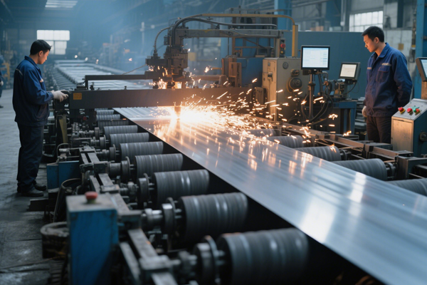
The alignment is no accident. Cold rolled silicon steel begins as a thicker hot-rolled band, then passes through repeated rolling reductions with carefully controlled annealing in between. During the final high-temperature anneal, a small number of favourably oriented grains grow at the expense of the rest. Metallurgists call this secondary recrystallisation, and the texture it produces is widely known as Goss texture. Mills keep the steel essentially single-phase throughout the process, because a phase change would destroy the alignment they have just built.
Because the processing window is so narrow, buyers pay a premium. Few mills hold the texture consistently from coil to coil, so batch consistency matters as much as a single impressive number.
What the Numbers on a Coil Actually Mean
Buyers usually meet a long list of figures before they see a coil. Each answers a different question; none means much in isolation.
| Figure | Common range | What it changes | The trade-off |
| Thickness | 0.23 / 0.27 / 0.30 / 0.35 mm | Eddy-current loss, stacking factor, handling | Thinner cuts loss but raises cost and fragility |
| Width | 700–1200 mm before slitting | How many laminations fit a core design | Wider coils need accurate slitting to avoid waste |
| Core loss (P1.7/50) | W/kg at 1.7 T and 50 Hz, measured along the rolling direction | No-load loss, and so lifetime running cost | Lower values demand tighter process control |
| Magnetic induction (B8) | Tesla at a stated field strength | How small and light the core can be | Higher-induction grades are harder to source |
| Surface coating | Thin insulating layer | Resistance between stacked laminations | The layer must survive punching and stacking |
| Standard system | IEC, EN, ASTM, JIS, GB | How loss and induction get measured | Results are not directly interchangeable |
Silicon steel is judged on magnetic behaviour rather than tensile strength, so a grade that looks strong on a mechanical test report may say nothing about how a core performs. When two offers share the same thickness, the loss value usually gives the more useful comparison — provided both were measured at the same induction and frequency.
Buyers should pay more attention to the coating. Stacked laminations must stay electrically separate; otherwise currents jump between sheets and rebuild the loss the thin gauge was meant to remove. A sound coating also helps punching tools run cleanly, since burrs along a cut edge can short neighbouring laminations.
Why thinner is not automatically better
Ordering the thinnest sheet available is tempting. Resistance to circulating currents does improve as the gauge drops, but three other things move in the wrong direction. Thin material costs more per tonne. It deforms more readily during slitting and stacking. Since every lamination carries an insulating layer, thinner sheets also mean more layers and less active steel inside the same core window. Most designers pick the thickest gauge that still meets the loss target, rather than the lowest number in a catalogue.
Where It Works — and Where It Does Not
The useful rule concerns the shape of the magnetic path, not the size of the machine. Where flux travels in a fixed loop, alignment pays off. Where it rotates, alignment becomes a liability.
- Power and distribution transformer cores, the largest use by volume
- Current transformers, voltage regulators and instrument transformers
- Reactors and other static magnetic devices with a defined flux path
- Large generators, in core designs where direction can be controlled
A motor rotor turns through a full 360 degrees, so the field inside it keeps changing direction relative to the sheet. Non-oriented silicon steel behaves almost the same in every direction, which is why it belongs in rotating machines. A directional grade would deliver excellent performance along one axis and poor performance everywhere else — the worst possible bargain. The two families are therefore not substitutes, even though both are called electrical steel.
Efficiency requirements reinforce the same logic. A distribution transformer can sit energised for decades, so a modest cut in no-load loss repays itself many times over. Tighter rules leave designers little room to step down a loss grade.
From Coil to Core: What Happens After Delivery
A coil that leaves the mill with a good loss value can perform worse by the time it reaches the core-building bench. The difference usually comes from the workshop rather than the steel.
Flux crossing the rolling direction loses the advantage the mill built in. Core builders therefore cut legs and yokes so the long, straight paths run along the easy axis, then join corners with angled joints that let the field turn gradually instead of cutting sharply across the grain.
Workshops also need to watch mechanical stress. Punching leaves a strained zone around every edge, and a tall burr can bridge two laminations. Clamp a stack too tightly and you raise both loss and the low humming noise a strained core produces. Some producers apply a tension coating that improves loss slightly; rough handling damages that layer easily.
For these reasons, a silicon steel supplier should state the tested loss for each coil, hold it steady from batch to batch, and protect the material from moisture in transit. Electrical sheet rusts quickly; even light corrosion can disturb the coating. Buyers who compare only the printed grade often discover these differences when the first core fails its loss test.
How cutting direction can undo the gain
Consider two identical coils slit into strips, one along the rolling direction and one across it. The strips look the same on the pallet, yet inside the core they behave nothing alike: the second set forces the flux to fight the grain for most of its path. Slitting plans, hole positions and joint geometry belong in the same conversation as the loss grade.
A Closer Look at One Cold Rolled Grain Oriented Coil
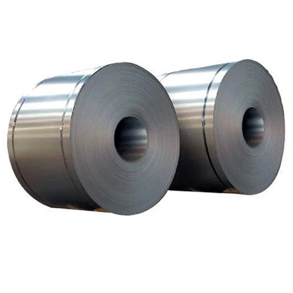
Buyers who need a directional grade in coil form can turn to Cold Rolled Grain Oriented Steel Coil, which covers the gauges most transformer cores use. Widths run from 700 to 1200 mm, with thicknesses of 0.23, 0.27, 0.30 and 0.35 mm available. Engineers can work to AISI, ASTM, BS, DIN, GB or JIS systems, and buyers can request ISO 9001, SGS and RoHS documentation. Transformer makers use it in small transformers, distribution units, large power transformers and generators, where low core loss and high permeability along the rolling direction set the efficiency of the finished machine.
How the rolling texture is held
Mills hold composition more tightly here than in non-oriented grades, since the texture depends on keeping the steel single-phase through the final anneal. Careful rolling and annealing develop the alignment; consistent thickness and an even coating then let laminations stack tightly without shorting. With that combination, a designer can build a smaller, lighter core for a given loss target.
Slitting, packaging and ready time
Runfei can slit wide master coils into the narrow widths a lamination line needs, which removes a processing step for the customer and cuts material waste. Coils ship in seaworthy packing: VCI moisture-proof paper, protective steel sheet and metal strapping, in either horizontal or vertical orientation. Runfei has cargo ready in around 35 days. For a workshop planning a production run, that slitting and packing detail is often as decisive as the loss grade itself.
Frequently Asked Questions
Why does grain direction matter for transformer efficiency?
Grain oriented means the crystals share one alignment, so the rolling direction magnetises far more easily than any other. A transformer’s flux follows a fixed path, and cutting the core along that easy axis takes less effort on every cycle, which keeps no-load loss low for every hour the unit stays energised.
Why is it not used in electric motors?
A motor’s magnetic field rotates continuously. A directional grade performs well along one axis and poorly along the others, so a rotating field would spend most of each cycle working against the material.
Does a thinner sheet always lower core loss?
It lowers eddy-current loss, which is only one part of the total. Cost, fragility, stacking factor and punching quality all worsen as the gauge drops, so designers choose the thickest sheet that still meets the loss target.
Can slitting or punching change the measured loss?
Yes. Cutting across the rolling direction, leaving burrs, introducing stress and damaging the insulating coating can all raise loss. A careful slitting plan and clean tooling protect the value paid for.
What should be confirmed before a coil is shipped?
Thickness and width, the loss value and the conditions under which it was measured, coating type, batch consistency, and how the coil will be protected from moisture during transport.
Conclusion
Grain direction is the quiet reason a transformer wastes less energy than it otherwise would. Once the crystals line up with the rolling direction, core builders can cut and stack the steel so the magnetic field follows the easiest path, and that saving repeats every hour the unit stays on the grid. Thickness, coating and workshop practice decide how much of the promise survives into the finished core, which is why the grade and the handling plan belong together. If you are reviewing core material for an upcoming transformer build, talk through your target loss, width and lamination layout with Runfei before the coil is slit.