The accelerating rollout of photovoltaic capacity is pushing structural support systems into ever harsher environments — from salt-laden coastal plains to permanently humid BIPV rooftops. Where conventional galvanized coatings begin to show edge bloom and wet-stack corrosion within a few seasons, project owners are looking for a more robust metallurgical answer. Zinc-aluminium-magnesium alloy-coated coil has emerged as that answer, and its adoption is now reshaping the way mounting structures are specified. This article walks through the dimensional, mechanical, and processing parameters that govern these advanced steel coils when they are cold-rolled into rails and brackets for building-integrated and ground-mounted solar applications. It focuses on the dimensional, mechanical, and processing parameters that a specialized mounting system manufacturer must control to deliver reliable, 25-year-plus service life.
Materials Science: Why the Zn–Al–Mg Coating Matters for Solar Infrastructure
Corrosion Resistance & Self–Healing Mechanism
The defining characteristic of ZAM steel is a dense, stable eutectic layer that forms when carefully metered additions of magnesium and aluminium are present in the coating. Whenever the strip is sheared, punched, or scratched in fabrication, corrosion products enriched with zinc, aluminum and magnesium gradually form a dense protective layer and react with atmospheric moisture, creating an insoluble film that seals the steel surface. This self-healing behaviour means that cut edges on a purlin or rail resist red rust far longer than the same detail on an ordinary galvanized product. For a mounting rail carrying dozens of punched slots and field-trimmed ends, that edge protection is what extends the maintenance-free interval of the entire array.
Life Cycle and Economic Value
Because its corrosion rate in C3 and C4 atmospheres is so low, a Zn-Al-Mg coated substrate can allow designers to specify thinner gauges in appropriate structural applications without compromising service life. The reduction in mass lowers material cost, transport weight, and the dead load imposed on a roof. Over the operational lifetime of a solar farm, those properties feed straight into a leaner operations and maintenance budget and a more predictable levelized cost of electricity.
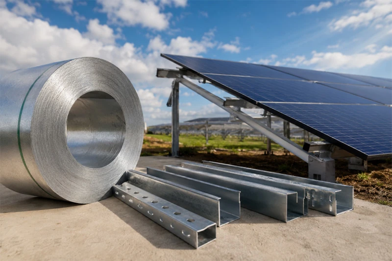
Core Technical Specifications for the Coated Coil
Mechanical Properties & Structural Steel Grades
For primary load-bearing members, high-strength structural grades are the preferred base material. High-strength Zn-Al-Mg coated structural grades such as S350GD+ZM are commonly specified for photovoltaic mounting systems. Where higher structural performance is required, structural steels such as S355JR may be used for thicker fabricated members rather than continuously coated sheet products. When a design calls for a tighter bend radius and a reduced sheet thickness, the specification may shift to a more formable grade such as S350GD+ZM; nevertheless, wherever a combination of high strength and reliable ductility is required, S355JR remains an effective and widely available reference.
Coating Mass Standards
Coating weight is selected to match the environmental severity class. For a normal urban or light-industrial BIPV roof, ZM90 to ZM120 is generally adequate. ZM275-ZM430, depending on project requirements, specified where saline mist or chemical residues are present.
Dimensional Tolerances
To achieve repeatable output on an automated roll-forming line, a competent mounting system manufacturer will impose a thickness tolerance of ±0.05 mm to ±0.08 mm, in accordance with EN 10143. That tight band keeps spring-back variation under control so that every metre of rail leaves the mill with an identical cross-section.
Rail Manufacturing & Technical Parameters
Roll–Forming Processing Parameters
When a Zn-Al-Mg coil is cold-rolled into C- and U-channel profiles, the minimum inside bend radius is normally held at R ≥ 1.5t. Respecting this threshold prevents micro-cracking of the coating on the tension face. The inherently higher yield point of ZAM steel means that the pass sequence and over-bend compensation must be carefully engineered so that the finished rail falls within the flatness and angularity tolerances the system design demands.
Punching and Cutting Tolerances
Mounting rails are pre-punched with slots that accept module clamps and structural fasteners. To let an installer align bolts without reaming or forcing, the positional tolerance on these features is typically maintained within ±0.2 mm. Precision flying-shear or servo-slitting systems are used to preserve the metallic coating right up to the cut face, so that the alloy’s self-healing property is fully retained.
Profile Geometry for Solar Rails
The cross-sections most commonly chosen for a photovoltaic bracket rail are C-channel, U-channel, and hollow structural profiles. Dimensional control on rail height, width, and flange bend is held to within ±0.5 mm, which allows standardised mid-clamps and end-clamps to engage without play or binding. When a solar mounting bracket is assembled from components that fit this precisely, the resulting connections consistently pass both static and dynamic load testing.
Tailoring Coating Specifications for BIPV and Ground-Mounted Systems
BIPV Roofing Systems Requirements
Weight constraints on a roof demand a careful balance between strength and material thickness. For such applications, high-strength grades are often specified in gauges ranging from 1.2 mm to 2.0 mm, delivering the necessary structural capacity while keeping the dead load low enough for existing buildings.
Aesthetics and Chemical Barrier
Where the support structure also serves as a visible roofing element, pre-painted Zn-Al-Mg steel (PPZAM) is frequently adopted. The organic topcoat provides an additional barrier against acid rain and bird droppings, and it satisfies the architectural requirement for long-term colour stability. For a BIPV photovoltaic bracket, specifying the correct paint system over the metallic coating ensures that both the corrosion resistance and the visual appearance endure for decades.
Ground–Mounted Systems Requirements
Ground-mount structures must withstand higher wind and snow loads, which typically pushes sheet thickness into the 2.0-3.5 mm range. When posts are driven directly into soil, the specification must also address electrochemical corrosion. In such cases, a higher coating mass and supplementary surface treatments or passivation systems may be specified where required, guided by a site-specific corrosion assessment.
Compliance, Testing, and Manufacturing Quality Control
Standard Compliance
Every engineering specification for solar-grade coated steel should reference the applicable international standards. EN 10346 is the primary European norm for continuously hot-dip coated flat products, while ASTM A1046 serves a similar role in North American markets. A thorough mounting system manufacturer provides mill test certificates that verify grade, coating mass, and mechanical properties against those standards. This documentation gives the design engineer and the asset owner full traceability from the master coil through to the finished structure.
Key Engineering Tests
Validation protocols include neutral salt spray testing to ISO 9227, where scribed panels with premium Zn-Al-Mg coatings may achieve 2,000–3,000 hours of neutral salt spray resistance before red rust appears, depending on coating mass and test conditions that check for flaking after 180-degree bending around a prescribed mandrel.
Significance for High–Strength Grades
When high-strength structural grades are specified, tensile strength, yield strength, and elongation are verified for every production batch. The consistency of S355JR’s mechanical properties directly determines the load-bearing capability of the finished rail, and it is this predictability that makes structural optimisation possible without over-engineering.
Conclusion
The long-term performance of a solar mounting structure hinges on three parameters: coating integrity, base-metal strength, and manufacturing precision. When those parameters are specified correctly — and when a qualified mounting system manufacturer verifies them at every stage of production — the resulting support system installs quickly, withstands the environment, and demands very little intervention. Runfei’s engineering team is available to supply detailed mill certificates, salt-spray test reports, and project-specific customisation support, helping you select the right material and profile geometry for your next BIPV or ground-mount development.


